
How does moisture change the thermal performance of backfill?
Traditional pea gravel surrounds can exhibit widely different thermal properties. Indicative values for general gravel range from approximately 0.5 to 0.6 m·K/W when saturated to 2.5 to 3.3 m·K/W when dry. These are reference estimates rather than certified values for a particular pea gravel supply. Lower thermal resistivity means heat can escape more readily.
Moisture content and groundwater levels may vary substantially with season, drainage and local ground conditions. Installation within clay does not demonstrate that the gravel will remain saturated. Conditions observed during construction may therefore differ considerably from those experienced during operation.
Cable heating can also drive moisture away from the installation, creating a local region of higher thermal resistivity. This increases resistance to heat flow and can raise conductor temperatures further. A design that relies on favourable wet conditions may consequently overestimate cable capacity. See the SINTEF research on moisture migration around buried cables.
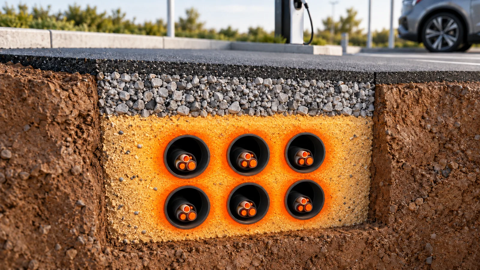
Is there an economical specification route?
ENA TS 97-1, Issue 2 (2016), Special backfill material for cable installations provides a useful reference for economical specification. Its traditional gravel/sand and cement-bound sand options have maximum dry thermal resistivity of 1.2 m·K/W, subject to the associated material and installation requirements.
This provides a basis for assessing conventional, verified materials before specifying premium thermal products. The specification should identify the required thermal performance, material acceptance criteria, placement requirements and site verification.
Better backfill or more copper?
Other engineered backfill systems can offer substantially higher thermal conductivity, and therefore lower thermal resistivity, than conventional surrounds. Their additional cost is worth comparing with the potential reduction in copper required for charging cables.
Where thermal capacity determines cable size, improved heat dissipation may allow a smaller conductor cross section or fewer parallel cables. The economic comparison should therefore consider the complete installation: backfill supply and placement, cables, terminations, pulling operations and any changes to duct or trench requirements.
A more expensive backfill can potentially produce a less expensive charging installation. That saving must be demonstrated through calculation. Voltage drop, fault withstand, protection requirements and installation constraints may still determine the minimum cable size. Smaller conductors can also increase operating losses, so capital savings should be assessed alongside lifetime energy costs.
What about strength and settlement?
Thermal performance must be achieved alongside adequate mechanical support. Backfill must sustain anticipated loading without unacceptable deformation or settlement.
Continuous support beneath and between ducts, suitable compaction, stable trench formation and properly constructed reinstatement layers all contribute to this outcome. High compressive strength alone cannot compensate for concealed voids or inadequate bedding.
The material and installation method must therefore suit the actual duct arrangement and available working space. Density, placement quality and settlement resistance deserve attention alongside any specified strength.
Why model the complete installation?
Thermal modelling using the IEC 60287 series, with an appropriate method for representing multiple material regions, can account for different backfill layers and surrounding ground properties. The assessment should represent cable and duct positions, dimensions and individual material properties, together with mutual heating between circuits. Our article on IEC 60287 cable thermal analysis covers the method.
The local duct surround, surrounding soil, Type 1 subbase and final surfacing should be distinguished where their properties differ. Improving the immediate surround reduces one part of the thermal resistance; the wider ground remains part of the heat dissipation path.
For EV charging infrastructure, the assessment should also reflect expected demand and loading duration. Comparing backfill and cable options together supports a more defensible design with lower uncertainty and reduced risk, while directing expenditure towards demonstrated performance.
Edition note: the linked document is Issue 2. ENA lists Issue 3 (2021) as current; new specifications should reference the applicable current edition and network owner requirements.