
How do hazardous zones influence the layout?
The first step is to establish the extent of the site's hazardous areas using the hazardous-area classification drawings and a suitable site survey. This includes permanent zones and temporary zones associated with activities such as tanker unloading.
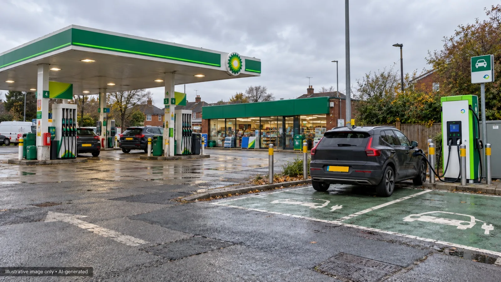
The assessment must consider the charging equipment, the vehicle being charged, and the full reach of the charging cable and connector. Positioning a charger outside a hazardous zone is insufficient if its cable allows a vehicle to charge within that zone.
The location of fuel dispensers, tank fill points, vent pipes and delivery positions therefore influences where charging bays can be provided. Site gradients and drainage also matter: a fuel spill must be considered where it could flow towards the charging area.
These constraints should be established before the equipment layout is fixed, with input from the person responsible for the site's DSEAR assessment.
Why do cable routes need the same attention as charging bays?
A remote power cabinet and satellite dispensers can offer flexibility in the forecourt layout, but the underground DC routes need careful coordination.
The IET/APEA filling-station guidance states that the DC cables between separated power-conversion equipment and dispensers must not pass through or beneath hazardous areas. It also addresses the routing of new network supply cables around permanent and temporary hazardous zones.
A route that appears convenient on a general arrangement drawing may therefore be unsuitable once the hazardous-area information is overlaid.
Underground chambers, existing services and duct entries also need assessment. Ducts can provide a route for vapour migration, so sealing arrangements form part of the design alongside mechanical protection and cable thermal performance.
How should earthing be considered across the site?
The existing forecourt earthing arrangement must be established before the protective measures for the EV installation are selected.
The IET/APEA supplement identifies TT and a dedicated, guaranteed TN-S arrangement as the supply-earthing options for charging equipment at filling stations. The conditions attached to those arrangements require careful review with the network operator.
Where the forecourt uses TT earthing, extending the charging installation into a coordinated site-wide TT system may be appropriate. This requires verification of the existing electrodes, protective conductors and bonding, together with the design of the residual-current protection.
An electrode resistance value alone does not establish that the arrangement is suitable. The designer must consider protective-device settings, disconnection times and the applicable touch-voltage criteria.
The design must also prevent unintended connections to a network or substation earth where separation is required. Cable armour, metallic containment, auxiliary supplies and communications cabling all need to be included in that assessment.
What about simultaneous contact and transferred potentials?
Where different earthing systems remain present, the assessment must consider whether a person could touch conductive parts associated with both systems at the same time.
This includes the vehicle on charge and nearby lighting columns, fences, building metalwork, equipment enclosures and other accessible conductive parts. The range of possible vehicle positions matters as much as the nominal bay outline. Our article on simultaneous contact risk sets out the assessment.
Separation below ground also needs consideration. Earth electrodes and buried metalwork can transfer potential between systems without an obvious connection above ground.
Where a new substation is provided, earth potential rise during an HV fault introduces a further design consideration. Its position and earthing arrangement need coordination with the forecourt's buried tanks, pipework and other conductive infrastructure. A specialist earthing study may be necessary to establish whether the proposed arrangement is practical.
How is the EV installation linked to the forecourt controls?
A separately supplied charging installation needs a defined response to the forecourt's emergency switching and normal site-closure controls.
Without that coordination, operating the existing forecourt emergency switch could leave the EV supply energised.
The design should identify which supplies are controlled, which devices perform the switching, and how the control signal reaches them. These requirements should be agreed before the feeder pillar is manufactured so that the necessary releases, control supplies, interfaces and operating mechanisms are included.
The IET/APEA supplement also recommends an interlock that disables charging when the filling station is closed. This operating requirement should be addressed alongside emergency switching.
Why use a fibre optic bridge?
A fibre-optic bridge allows a control signal to pass between the forecourt controls and the EV switchgear without using a copper signal connection between the two locations.
This is particularly useful where a conductive control cable could compromise the intended separation of earthing systems or introduce transferred potentials.
An all-dielectric fibre cable avoids a metallic path within the fibre cable itself. Where fibre contains metallic armour or other conductive components, those elements still require assessment. Other links between the installations, including data cabling, must also be reviewed.
Fibre provides the communication medium; the complete control arrangement still needs a defined and verified safety function.
How should the failure and reset behaviour be designed?
One approach is an energised-to-run control arrangement operating an undervoltage release on the EV supply circuit-breaker.
In this arrangement, a healthy control signal permits the supply to remain connected. Operation of an emergency switch removes that permission and causes the switching device to open.
The design must also address loss of control power, interruption of the fibre link and relevant interface failures. A fibre converter should not be assumed to provide the required failure behaviour simply because it can transmit a contact signal.
Resetting the emergency switch and restoring power are separate actions. Reinstating a healthy signal should not automatically restart the installation. Reclosure should require a deliberate action by an authorised person after the cause of the shutdown has been investigated.
Where remote reclosure from the shop is provided, the switching mechanism and control logic must support that function while preventing closure whenever the emergency circuit remains unhealthy.
What does commissioning the complete arrangement involve?
Commissioning needs to prove the interaction between the forecourt and the charging installation.
The agreed test procedure should verify emergency switching, normal closure, loss of control power, interruption of the fibre link and the reset sequence. The results should demonstrate the behaviour specified in the design.
Earthing measurements, protective-device settings and disconnection performance must also be verified and recorded. Handover information should clearly identify separate supplies, earthing arrangements, control interfaces and operating instructions.
EV charging at a filling station requires close coordination between the electrical designer, hazardous-area specialist, network operator, switchgear manufacturer and installing contractor. Resolving those interfaces early helps produce an installation that can be operated, maintained and expanded with a clear understanding of how its safety measures work.
EV Design provides specialist electrical design support for EV charging infrastructure, including supply distribution, earthing, protection coordination and integration with existing site controls.
Technical references
- APEA/Energy Institute, Design, Construction, Modification, Maintenance and Decommissioning of Filling Stations (the “Blue Book”), fifth edition, November 2024.
- IET/APEA, Guide to Electric Vehicle Charging Installations at Filling Stations, second edition, 2025, used alongside the IET Code of Practice for Electric Vehicle Charging Equipment Installation and the applicable edition of BS 7671.